Fluke 718 Pressure Calibrator
General Specifications
- Maximum voltage: 30 volts: Non-operating
- Temperature: -40 °C to 60 °C
- Operating temperature: -10 °C to 55° C
- Relative humidity: 95 % (10 °C to 30 °C); 75 % (30 °C to 40 °C); 45 % (40 °C to 50 °C); 35 % (50 °C to 55 °C)
- Operating altitude: 3,000 m max
- Shock: 1 m drop test
- Vibration: Random, 2 g, 5 Hz – 500 Hz
- Safety: CSA C22.2 No. 1010.1: 1992
- EMC: EN50082-1: 1992 and EN55022: 1994 Class B
Size/weight (717 with holster): 201 mm x 98 mm x 52 mm (7.93 in x 3.86 in x 2.06 in) 600 g (21 oz)
Size/weight (718 with holster): 216 mm x 94 mm x 66 mm (8.50 in x 3.72 in x 2.60 in) 992 g (35 oz)
Power: 9V battery ANSI/NEDA 1604A or IEC 6LR619V alkaline; two batteries in 718
Battery Life: 4 to 20 hours typical, depending on functions used
Warranty: Three years (one year on pressure pump in Fluke 718)
Display: LCD, 5 digit pressure and current simultaneous
Accuracy: 0.05 %
Note: For use with non-corrosive gasses
The New 718 Calibrator Pump
The new Fluke 718 is a uniquely protected pneumatic pressure calibrator and pump. The new pump design uses protective check valves that allow air to pass through the pump for calibration but inhibits fl uids from entering the pump and causing damage. These two check valves allow the bi-directional fl ow of air into or out of the 718. Even after draining the process fl uid from the calibration port of the device under test, minute amounts of process fluids may often still be lurking behind. In the event these fluids enter the 718 pump cavities, the new pump design enables quick cleaning and maintenance, even in the field.
Pump valve assembly cleaning instructions
1. Using a small screwdriver, remove the two valve retention caps located in the oval shaped opening on the underside of the Calibrator.
2. After the caps have been removed, gently remove the spring and o-ring assembly.
3. Set aside the valve assemblies in a safe area and clean out the valve body using a cotton swab soaked in IPA (isopropyl alcohol).
4. Repeat this process several times using a new cotton swab each time until there is no remaining sign of residue.
5. Pump the unit several times and check again for residue.
6. Clean the o-ring assembly and o-ring on the retention caps with IPA and inspect the o-rings closely for any cuts, nicks, or wear. Replace if needed.
7. Inspect the springs for wear or loss of tension. They should be approximately 8.6 mm long in the relaxed state. If they are shorter than this, they may not allow the o-ring to
seat properly. Replace if needed.
8. Once all parts have been cleaned and inspected, reinstall the oring and spring assemblies into the valve body.
9. Reinstall the retention caps and gently tighten the cap.
10. Seal the output of the Calibrator and pump up the unit to at least 50 % its rated pressure.
11. Release the pressure and repeat several times to ensure that the o-rings seat properly.
The Calibrator is now ready for use.

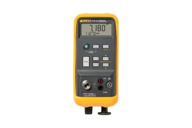
 fluke-718
